



You are here

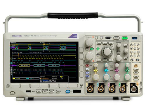
Oscilloscope Tektronix MDO3000

$ 5,650.00
                                                         
Origin: Germany                                               Pedido N° ref.:  MDO3000
 Shipping: throughout Latin America                                                    Delivery time: Inquire 
See TEKTRONIX Oscilloscopes   View list Oscilloscope in another brand
View products TEKTRONIX                      Buy   
Details
Six instruments. An oscilloscope. Infinite versatility.
The MDO3000 Mixed Domain Oscilloscope features six built-in instruments, including a spectrum analyzer, function generator and more, giving you the ability to capture analog, digital and RF signals with a range
beneficios
Mixed domain of the oscilloscope - integrated spectrum analyzer Each model comes standard with an integrated spectrum analyzer, allowing you to analyze RF signals up to the nominal bandwidth of the application range. MDO3SA option extends the frequency coverage of the spectrum analyzer to 3 GHz.
Ola Inspector® dedicated navigation controls on the front panel allow for easy zooming and navigation through 10 Mpoint records. Automated search capability quickly finds and marks each occurrence of user-specified events.
Integrated, upgradable function/arbitrary generator The function generator saves space on the table and allows closed-loop testing by sensors that simulate or blocks of the unfinished system. Capture real signals and replicate them as arbitrary waveforms up to 128k points long, with a single instrument.
integrated logic analyzer, upgradable. Allows debugging of digital parts of embedded designs. Problem tracking system with broader visibility of the system.
serial and parallel bus for triggering and analysis to quickly debug your parallel and/or common serial buses with automatic triggering, decoding, and searching.
Integrated digital voltmeter and frequency counter free when registering the product! Allows for quick measurement of DC voltage, AC + DC RMS, AC RMS, and frequency.
Incredibly small form factor saves valuable lab space by integrating a spectrum analyzer, arbitrary function generator, logic analyzer, protocol analyzer, and DVM/counter into the debugging tool of choice - the oscilloscope. Only 5.8 inches deep and 9 pounds yet still offers a 9" WVGA display.
Upgrade capability I don't know what will work next year? Updates are available for analog bandwidth, frequency spectrum of the analyzer, arbitrary function generator, digital channels (MSO), trigger and serial analysis packages, and much more - the guarantee of utility in the coming years.
Offline waveform analysis allows for better time and resource utilization; view, measure, and analyze captured data in your laboratory, independent of hardware reach with TekScope Anywhere
analog channels vertical system
hardware bandwidth limits
≥350 MHz models at 20 MHz or 250 MHz and 200 MHz100 MHz models at 20 MHz
AC, DC input coupling
Input impedance 1 MW ± 1%, 50 Ω ± 1%, 75 Ω ± 1%; 75 Ω not available in 1 GHz models
input sensitivity range
1 MW 1 mV / div a 10 V / Div50 Ω, 75 Ω 1 mV / div a 1 V / div
Vertical resolution of 8 bits (11 bits with Hi Res)
Maximum input voltage
1 MW 300 V RMS CAT II with peaks ≤ ± 425 V 50 Ω, 75 Ω 5 V RMS with peaks ≤ ± 20 V
DC achieves an accuracy of ± 1.5% for 5 mV/div and above, with a reduced rate of 0.10%/°C above 30 °C
± 2.0% for 2 mV / div, with a reduced rate of 0.10% / °C above 30 °C
± 2.5% at 1 mV / div, with reduced rate at 0.10% / °C above 30 °C
± 3.0% variable gain, derated 0.10% / °C above 30 °C
Channel-to-channel isolation (typical) Any of the two channels at the vertical scale equal ≥100: 1 at ≤100 MHz and ≥30: 1 at > 100 MHz bandwidth at the score
Random noise (typical)
the establishment of 50 Ω, RMS vertical scale
MDO310x MDO305x MDO303x MDO302x MDO301x
1 mV / div 0,179 0,178 mV mV mV 0,169 0,178 0,161 mV mV
100 mV / div 2,4 mV 2,05 mV 1,97 mV 1,93 mV 1,87 mV
1 V / div 24.67 20.96 mV mV mV 20.01 19.39 18.55 mV mV
offset area
/ Offset adjustment range volts
Input 1 M Ω 50 Ω, 75 Ω input
1 mV / div a 50 mV / div ± 1 V ± 1 V
50,5 mV / div a 99,5 mV / div ± 0,5 V ± 0,5 V
100 mV / div a 500 mV / div ± 10 V ± 10 V
505 mV / div a 995 mV / div ± 5 V ± 5 V
1 V / div a 10 V / div ± 100 V ± 5 V
horizontal analog channels system
time base range
1 GHz modelos 400 ps / div a / div≤ 500 modelos 1000 MHz s 1 ns / div a 1000 s / div
Maximum duration of highest sampling frequency (all channels/means)
1 GHz modelos 4/2 modelos ms≤ 500 MHz 4/4 ms
Time delay base of interval -10 divisions to 5000 s
channel-to-channel skew adjustment of ± 125 ns
Base time accuracy of ± 10 ppm over any interval ≥1 ms
firing system
Automatic, normal, and single trigger modes
DC, AC trigger coupling, HF suppression (attenuates > 50 kHz), LF rejection (attenuates < 50 kHz), noise rejection (reduces sensitivity)
Trigger hold range of 20 ns to 8 s
Trigger at Edge type sensitivity (typical), DC coupled
Trigger source sensitivity
Any analog channel input For 1 mV / div to 4.98 mV / div; 0.75 div from DC to 50 MHz, increasing to 1.3 div in the instrument's bandwidth
≥ 5 mV / div: 0.40 div from DC to 50 MHz, increasing to 1 div in the instrument's bandwidth
In aux (external); available in two-channel instruments at 200 mV from DC to 50 MHz, increasing to 500 mV at 200 MHz
landline
trigger level ranges
Any input channel ± 8 divisions from the center of the screen, ± 8 divisions from 0 V when LF vertical rejection coupling is selectedAux In (external) ± 8 VLine The line activation level is set at 50% of the mains voltage.
trigger frequency reading provides 6 digits frequency reading of activatable events.
types of triggers
Positive, negative edge, or the slope on any channel. Coupling includes DC, AC, HF rejection, LF rejection, and noise rejection. Trigger sequence (B-trigger) time delay: 8 ns to 8 s. Or event delay trigger: 1 to 4,000,000 events. Not available when "O" edge is selected. Pulse trigger by pulse width in positive or negative widths that are >, <, =, ≠, or within/outside a specified period of time. Timeout Trigger an event that remains high, low, or is, for a specified period of time (4 to 8 ns). Runt trigger on a pulse that crosses a threshold but cannot cross a second threshold before crossing the first again. Logic trigger when any logical pattern of the channels becomes false or remains true for a specified period of time. Any input can be used as a clock to search for the pattern on a clock edge. Pattern (AND, OR, NAND, NOR) specified for all input channels defined as high, low, or No Care. Setup and hold the trigger violations of both setup time and hold time between the clock and the data present on either the analog and digital input channels.
Establishment and retention type of trigger Description
Time interval setting -0.5 ns to 1.024 ms.
Hold Time interval from 1.0 ns to 1.024 ms
Configuration + Hold Time interval of 0.5 ns 2.048 ms
Rise/fall time of trigger at edge rates that are faster or slower than specified. Slope can be positive, negative, or the time and range is from 4.0 ns to 8 s. Trigger video on all lines, even, odd, or all data of NTSC, PAL, and SECAM video signals.
480p / 60, 576p / 50, 720p / 30, 720p / 50, 720p / 60, 875i / 60, 1080i / 50, 1080i / 60, 1080p / 24, 1080p / 24sF, 1080p / 25, 1080p / 30, 1080p / ⁠50, 1080p / 60
Order of two levels and three-level video synchronization standards.
Parallel (available when the MDO3MSO option is installed) triggers with a parallel bus data value. The parallel bus can be from 1 to 20 bits (from digital and analog channels) in size. Binary and hexadecimal roots are compatible.
acquisition system
acquisition modes
Acquire the sample samples values. Peak Detect Capture spurious as narrow as 1.5 ns (1 GHz models), 2.0 ns (500 MHz), 3.0 ns (350 MHz models), 5.0 ns (200 MHz models), 7.0 ns (100 MHz models) at all speeds. Averaging of 2 to 512 waveforms included in the envelope average. Envelope min-max peak detection reflects data across multiple acquisitions. Number of selectable envelope waveforms between 1 and 2000 and infinity. Hi Res real-time averaged load wagon reduces random noise and vertical increases waveform resolution. Roll scroll left to right across the screen at sweep speeds slower than or equal to 40 ms/div. FastAcq® optimizes the instrument for dynamic signal analysis and capturing rare events, capturing > 280,000 WFMS/s at 1 GHz and models > 235,000 WFMS/s from 100 MHz - 500 MHz models.
waveform measurements
Waveform cursors and display
Automatic measurements (time domain) 30, of which up to four can be displayed on the screen at any given time. Measurements include: Period, frequency, delay, rise time, time, positive duty cycle, negative duty cycle of the drop, positive pulse width, negative pulse width, burst width, Phase, Positive Overshoot, Negative Overshoot, total excess, peak to peak, amplitude, high, low, Max, Min, average, cycle average, RMS, cycle RMS, positive pulse count, negative pulse count, Rising Edge Count, Falling Edge Count, areas and cycle.
Automatic measurements (3) frequency domain, of which one can be visualized on the screen at any given time. Measurements include the power supply channel, adjacent channel power ratio (ACPR), and occupied bandwidth (OBW)
Statistical measurements of mean, minimum, maximum, standard deviation.
Reference levels defined by the user for automatic measurements can be specified in any percentage or units.
Gating Isolate the specific event of an acquisition to take measurements in, using the screen or waveform cursors.
A waveform histogram provides a matrix of data values representing the total number of accesses within a user-defined region of the screen. A waveform histogram is both a visual graph of the hit distribution and a numerical matrix of values that can be measured.
Sources of Channel 1, Channel 2, Channel 3, Channel 4, Ref 1, Ref 2, Ref 3, Ref 4, MathTypes vertical, horizontal
waveform measurements histogram 12, of which up to four can be displayed on the screen at one time. Waveform counter, hits in the box, a peak matches, Median, Max, Min, peak to peak, average, standard deviation, Sigma 1, Sigma 2, 3 Sigma
waveform mathematics
Arithmetic to add, subtract, multiply, and divide waveforms.
mathematical functions integrate, differentiate, FFT
FFT spectral magnitude. Set FFT vertical scale to linear RMS or dBV RMS, and FFT Window to rectangular, Hamming, Hanning, or Blackman-Harris.
spectrum mathematics Add or subtract traces from the frequency domain.
advanced mathematics define algebraic expressions in great detail including waveforms, reference waveforms, mathematical functions (FFT, Intg, Diff, Log, Exp, sqrt, ABS, sine, cosine, tangent, Rad, Deg), scalars, up to two user-adjustable variables and results of parametric measurements (Period, Frequency, Delay, Rise, Fall, PosWidth, NegWidth, BurstWidth, Phase, PosDutyCycle, NegDutyCycle, PosOverShoot, NegOverShoot, TotalOverShoot, PeakPeak, amplitude, RMS, CycleRMS, high, low, Max, Min, Mean CycleMean, plots, surface, CycleArea, and trend). For example, (Intg (Ch1 - Mean (CH1)) × 1.414 × Q1)
Event Law
Events None, when a trigger occurs, or when a defined number of acquisitions completes (1 to 1000000)
Actions to stop acquisition, save waveform to a file, save screen image, print, AUX OUT pulse, remote SRQ interface, email notification, and visual notification
Repeat Repeat the treatment act of events (1 to 1,000,000 and infinity)
Modo Video Foto
Sources from Channel 1, Channel 2, Channel 3, Channel 4
Video standards NTSC, PAL
Manual contrast and brightness and automatic
Odd, even, interleaved selection field
Selectable image location on screen X and Y location, width and height adjustment, output line and pixel line, and line-to-line lateral shift control.
Power measurements (optional)
Power quality measurements V RMS, VCrest Factor, frequency, IRMS, ICrest Factor, real power, apparent power, reactive power, power factor, phase angle.
Change of loss measurements
Power loss Ton Toff, conduction, total loss. Energy Ton Toff, conduction, total.
THD-F, THD-R, RMS measurements. Graphs and table show harmonics. Testing for IEC61000-3-2 Class A and MIL-STD-1399, Section 300A.
measurements of VRipple and IRipple.
modulation analysis Graphical representation of + Pulse Width, Pulse-width, period, frequency, duty cycle +, and -Duty types of modulation of the cycle.
Safe operating area Graphical display and mask tests to change the measurements of the safety device's operating area.
dV / dt and dl / dt measurements cursor rise speed measurements
limit tests / mask (optional)
Limit test source: Any Ch1 - CH4 or any R1 - R4
mask test: Any Ch1 - CH4
Vertical tolerance limit test for mask creation from 0 to 1 in 1 m division increments; Horizontal tolerance limit test from 0 to 500 m in 1 m division increments.
custom mask Load from text file with up to 8 segments.
Mask scaling lock for source code in (automatically mask re-scales with the source setting of channel changes)
Lock to the OFF Source (mask does not scale with channel source adjustments)
Test criteria are executed until the minimum number of waveforms (from 1 to 1,000,000 and Infinity)
minimum elapsed time (from 1 second to 48 hours and infinity)
violation threshold From 1 to 1,000,000 and Infinity
Actions on the failure of image acquisition test stop screen, save to a file, save the waveform screenshot image to a file, pulses, AUX OUT, set SRQ remote interface
Actions in the complete AUX OUT pulse test, SRQ remote interface adjustment
Display status test results, total waveforms, number of violations, total tests, tests, elapsed time, total accesses not for each segment of the mask
2 - Spectrum analyzer
MDO3012 capture bandwidth, MDO3014 models: 100 MHz
MDO3022, MDO3024 modelos: 200 MHz
MDO3032, MDO3034 modelos: 350 MHz
MDO3052, MDO3054 modelos: 500 MHz
MDO3102, MDO3104 modelos: 1 GHz
All models: 3 GHz with MDO3SA option
Span MDO3012, MDO3014 modelos: 9 kHz - 100 MHz
MDO3022, MDO3024 modelos: 9 kHz - 200 MHz
MDO3032, MDO3034 modelos: 9 kHz - 350 MHz
MDO3052, MDO3054 modelos: 9 kHz - 500 MHz
MDO3102, MDO3104 modelos: 9 kHz - 1 GHz
All models: 9 kHz - 3 GHz with MDO3SA option, in a 1-2-5 sequence.
Resolution bandwidth of 20 Hz - 150 MHz in a sequence of 1-2-3-5
Reference level -130 dBm to +20 dBm in 5 dBm steps
The vertical scale of 1 dB / div to 20 dB / div in a 1-2-5 sequence
Vertical position -100 to +100 divs (displayed in dB)
unidades verticales dBm, dBmV, dBmV, dBμW, DBMA, dBμA
average noise level (DANL)
9 kHz - 50 kHz <-109 dBm / Hz (<-113 dBm / Hz typical) 50 kHz - 5 MHz <-126 dBm / Hz (<-130 dBm / Hz typical) 5 MHz - 2 GHz <-136 dBm / Hz (<-140 dBm / Hz typical) 2 GHz - 3 GHz <-126 dBm / Hz (<-130 dBm / Hz typical)
DANL with TPA-N-PRE attached preamplifier set to "Auto", and the reference level adjusted to -40 dB
9 kHz - 50 kHz <-117 dBm / Hz (<-121 dBm / Hz typical) 50 kHz - 5 MHz <-136 dBm / Hz (<-140 dBm / Hz typical) 5 MHz - 2 GHz <-146 dBm / Hz (<-150 dBm / Hz typical) 2 GHz - 3 GHz <-136 dBm / Hz (<-140 dBm / Hz typical)
spurious response
2nd harmonic distortion (> 100 MHz) <-55 dBc (<-60 dBc typical) 3rd harmonic distortion (> 100 MHz) <-53 dBc (<-58 dBc typical) 2nd order intermodulation distortion (> 15 MHz) <-55 dBc (<-60 dBc typical) 3rd order intermodulation distortion (> 15 MHz) <-55 dBc (<-60 dBc typical)
la respuesta residual
<-78 DBm (≤ -15 dBm and RF input reference level terminated with 50 Ω)
A 2,5 GHz <-67 DBMAT 1,25 GHz <-76 dBm
Crosstalk spectrum analyzer channels of the oscilloscope
≤800 input frequencies MHz <-60 dB from the reference level (typical)> 800 MHz - 2 GHz input frequencies <-40 dB from the reference level (typical)
Phase noise at 1 GHz CW
10 kHz <-81 dBc / Hz, <-85 dBc / Hz (typical) 100 kHz <-97 dBc / Hz, <-101 dBc / Hz (typical) 1 MHz <-118 dBc / Hz, <-122 dBc / Hz (typical)
Level Reference level measurement uncertainty 10 dBm to -15 dBm. The input level ranges from the reference level to 40 dB below the reference level. Specifications exclude matching error.
18 °C - 28 °C <± 1.2 dBm (<± 0.6 dBm typical) Above operating range <± 2.0 dBm
measurement uncertainty of level with TPA-N-PRE preamplifier attached, preamplifier mode set to 'Auto'. Reference level of 10 dBm adjusted to -40dBm. The input level ranges from the reference level to 30 dB below the reference level. Specifications exclude mismatch error.
18 °C - 28 °C <± 1.5 dBm (typical) or preamplifier state Over operating range <± 2.3 dBm either preamplifier state
measurement accuracy of frequency ± ((x [Frequency error reference] [Frequency marker]) + / 750 + 2) Period () Hz; Frequency error reference = 10 ppm (10 Hz / MHz)
Maximum input operating level
dBm average continuous power 20 (0.1 W) DC maximum before damage ± 40 V DC Maximum power before damage (CW) +33 dBm (2 W) Maximum power before damage (pulse) +45 dBm (32 W) (<10 microseconds pulse width, <1% duty cycle, and reference level of ≥ 10 dBm)
Maximum operating input level with attached TPA-N-PRE preamplifier
dBm average continuous power 20 (0.1 W) DC maximum before damage ± 20 V DC Maximum power before damage (CW) +30 dBm (1 W) Maximum power before damage (pulse) +45 dBm (32 W) (<10 microseconds pulse width, <1% duty cycle, and reference level of ≥ 10 dBm)
normal frequency tracking domain types, Normal, Max Hold, Hold Min
Detection methods + Peak, -peak, Normal, Sample
automatic markers One of eleven peaks identified based on threshold values and user-adjustable excursions
manual markers Two manual markers indicating frequency, amplitude, noise density, and phase noise
absolute or Delta marker measurements
ventanas FFT
Factor ventana FFT
Kaiser 2.23
rectangular 0,89
Hamming 1.30
Hanning 1,44
Blackman-Harris 1.90
Flat-Top 3,77
3 - Arbitrary function generator
(Option MDO3AFG Required)
Sine, square, pulse, ramp / triangle, DC, noise, sin(x) / x (Sinc), Gaussian, Lorentz, exponential rise, exponential decay, Haversine, cardiac, and arbitrary waveforms.
Seno
frequency range of 0.1 Hz to 50 MHz Amplitude range of 20 MVP-p to 5 Vp-p in Hi-Z; 10 MVP-p to 2.5 Vp-p in 50 Ω Amplitude flatness (typical) ± 0.5 dB at 1 kHz (± 1.5 dB for 20 <MVP-p amplitudes) Total harmonic distortion (typical) of 1% at 50 Ω
2% for amplitude <50 mV and frequencies > 10 MHz
3% for amplitude <20 mV and frequencies > 10 MHz
Spurious dynamic range free (SFDR) (typical) -40 dBc (Vp-p ≥ 0.1 V); -30 dBc (Vp-p ≤ 0.1 V), 50 Ω load
Square / Pulso
Frequency range from 0.1 Hz to 25 MHz Amplitude range from 20 mVp-p to 5 Vp-p in Hi-Z; 10 mVp-p to 2.5 Vp-p in 50 Ω Duty cycle from 10% to 90% or 10 ns minimum pulse width, which is the greater cycle resolution Duty 0.1% minimum pulse width (typical) 10 ns Rise / fall time (typical) 5 ns (10% - 90%) pulse width resolution 100 ps Overshoot (typical) <2% for signal stages above 100 mV Asymmetry ± 1% ± 5 ns, at 50% cycle Jitter duty (TIE RMS) (typical) <500 ps
Ramp / Triangle
frequency range from 0.1 Hz to 500 kHz Amplitude 20 mVp-p to 5 Vp-p in Hi-Z; 10 mVp-p to 2.5 Vp-p in 50 Ω symmetry Variable 0% to 100% resolution Symmetry 0.1%
corriente continua
level range (typical) ± 2.5 V in Hi-Z; ± 1.25 V in 50 Ω
ruido
Amplitude range 20 MVP-p to 5 Vp-p in Hi-Z; 10 mVp-p to 2.5 Vp-p in 50 Ω Amplitude resolution 0% to 100% in increments of 1%
Sin (x) / x (Sinc)
Typical frequency range from 0.1 Hz to 2 MHz Amplitude 20 MVP-p at 3.0 Vp-p in Hi-Z; 10 MVP-p at 1.5 Vp-p in 50 Ω
gaussiano
Typical frequency range from 0.1 Hz to 5 MHz Amplitude 20 MVP-p to 2.5 Vp-p in Hi-Z; 10 MVP-p to 1.25 Vp-p in 50 Ω
Lorentz
Typical frequency range from 0.1 Hz to 5 MHz Amplitude 20 MVP-p at 2.4 Vp-p in Hi-Z; 10 MVP-p at 1.2 Vp-p in 50 Ω
Aumento exponencial / Decay
Typical frequency range from 0.1 Hz to 5 MHz Amplitude 20 MVP-p to 2.5 Vp-p in Hi-Z; 10 MVP-p to 1.25 Vp-p in 50 Ω
Haversine
Typical frequency range from 0.1 Hz to 5 MHz Amplitude 20 MVP-p to 2.5 Vp-p in Hi-Z; 10 MVP-p to 1.25 Vp-p in 50 Ω
Cardiac (typical)
Frequency range from 0.1 Hz to 500 kHz Amplitude 20 mV-p to 5 Vp-p in Hi-Z; 10 mV-p to 2.5 Vp-p in 50 Ω
Arbitrario
memory depth of 1 to 128 range kAmplitude 20 MVP-p at 5 Vp-p in Hi-Z; 10 MVP-p at 2.5 Vp-p in 50 Ω Repetition rate of 0.1 Hz to 25 MHz Sample rate of 250 MS/s
frequency accuracy
sine wave and ramp of 130 ppm (frequency <10 kHz)
50 ppm (≥ frequency of 10 kHz)
square wave and pulse of 130 ppm (frequency <10 kHz)
50 ppm (≥ frequency of 10 kHz)
Resolution 0.1 Hz or 4 digits; whichever is greater
amplitude accuracy ± [(1.5% peak to peak amplitude adjustment) + (1.5% DC offset adjustment) + 1 mV] (frequency = 1 kHz)
desplazamiento DC
DC offset range of ± 2.5 V in Hi-Z; ± 1.25 V in 50 Ω DC offset resolution of 1 mV in Hi-Z; 500 uV in 50 Ω Offset accuracy of ± [(1.5% of the absolute compensated voltage value) + 1 mV]; derated 3 mV for every 10 °C, protected from 25 °C
The ArbExpress® MDO3000 is compatible with the PC-based signal generator waveform creation ArbExpress® and editing software. Capture waveforms in the MDO3000 oscilloscope and transfer them to ArbExpress for editing. Create complex waveforms in ArbExpress and transfer them to the arbitrary function generator in the MDO3000 for output. To download the ArbExpress software, go to www.tektronix.com/downloads.
4 - Logic analyzer
(MDO3MSO Option Required)
16 digital input channels (D15 to D0)
Thresholds Threshold per set of 8 channels
TTL, CMOS, ECL, PECL threshold selections, user-defined
User-defined series of thresholds from -15 V to +25 V
Maximum input voltage of -20 to +30 V
Precision threshold ± [100 mV + 3% of threshold value]
Dynamic input range 50 Vp-p (setting depends on the threshold)
Minimum voltage swing of 500 mV
Input resistance 101 kW
Load probe 8 pF
Vertical resolution of 1 bit
Digital channels of the horizontal system
(MDO3MSO Option Required)
maximum sample rate (Main) 500 MS/s (2 ns resolution)
maximum recording length (Main) 10 M
Maximum sampling frequency (MagniVu) 8.25 GS/s (121.2 ps resolution)
maximum recording length (MagniVu 10k centered on the trigger
minimum detectable pulse width (typical) 2 ns
channel-to-channel asymmetry (typical) 500 ps
The maximum input trigger rate is 250 MHz (maximum frequency sine wave that can be accurately reproduced as a square wave of logic. Requires the use of short mass extenders on each channel. This is the maximum frequency at minimum oscillation amplitude. Higher trigger rates can be achieved with higher amplitudes.)
5 - Serial Protocol Analyzer
Automated Serial Triggering, Decode, and search options for I2C, SPI, / 422/485 / UART, USB 2.0, CAN, LIN, FlexRay, MIL-STD-1553, and audio buses RS-232.
For more detailed information about the bus support products, please refer to the
Series trigger and the data sheet of application modules Analysis.
6 - Digital voltmeter
Fuente Canal 1, Canal 2, Canal 3, Canal 4
types of measurement RMS AC, DC, RMS AC + DC (reads aloud in volts or amperes); Frequency
ACV, DCV resolution: 4 digits
Frequency: 5 digits
Frequency accuracy ± (10 μHz / Hz + 1 load)
Measurement rate 100 times/second; measurements updated on the screen 4 times/second
automatic vertical range adjustments Automatic adjustment of vertical settings to maximize the dynamic measurement range; available for any non-trigger source
Graph shows the graphical indication of minimum, maximum, current value, and five-second rolling range measurement
General product specifications
Pantalla tipo 9 pulg. (229 mm) pantalla a color
Screen resolution 800 × 480 pixels vertical horizontal (WVGA)
Interpolation Without (x) / x
Waveform styles Vectors, points, variable persistence, infinite persistence.
FastAcq. Temperatura paletas, espectral, Normal, Invertido
Complete reticles, Grid, solid, cross-shaped, Frame, IRE, and mV
Format YT, XY, and simultaneous XY / YT
Maximum waveform capture rate > 280,000 WFMS / s in FastAcq acquisition mode at 1 GHz models
> 235,000 WFMS / s in FastAcq acquisition mode of 100 MHz - 500 MHz models
> 50,000 WFMS/s in DPO acquisition mode across all models
Input / output ports
High-speed USB 2.0 host port Compatible with USB mass storage devices, printers, and keyboards. One port on the front and one port on the back of the instrument.
rear panel connector USB 2.0 port device allows communication / control of the oscilloscope via USBTMC or GPIB (with a TEK-USB-488), and direct printing on PictBridge compatible printers.
Print output to the printer network, PictBridge printer, or an email-compatible printer. Note: This product includes software developed by the OpenSSL Project for use in the OpenSSL Toolkit. (Http://www.openssl.org/)
LAN RJ-45 port, compatible with 10/100 Mb/s
Video output port with female DB-15 connector, connect to display the oscilloscope screen on an external monitor or projector. SVGA resolution.
Auxiliary input (typical) (Available in two-channel models)
- Front panel input impedance of the BNC connector, 1 input MΩ Maximum 300 V RMS CAT II with peaks ≤ ± 425 V
Output voltage probe compensator and frequency pins on the front panel
Amplitud 0-2,5 VFrequency
1 kHz
Auxiliar a cabo panel trasero conector BNC
VOUT (Hi): ≥2.25 circuito abierto V, V ≥0.9 50 Ω a tierra
Us (Lo): ≤0.7 V over a load of ≤4 mA; ≤0.25 V 50 Ω to ground
The output can be configured to provide a signal output pulse when the oscilloscope triggers, a trigger signal from the internal arbitrary function generator, or an event out for limit/mask testing.
The rear panel security lock slot of Kensington style connects to the standard Kensington lock style.
VESA mounting standard (MIS-D 75) 75 mm VESA mounting points on the back of the instrument.
LAN extensions for Instrumentation (LXI)
Clase LXI Core 2011
V1.4 version.
Software
OpenChoice® desktop allows quick and easy communication between a Windows PC and the oscilloscope via USB or LAN. Transfer and save configurations, waveforms, measurements, and screen images. Word and Excel toolbars automate the transfer of acquisition data and screen images from the oscilloscope into Word and Excel for quick reporting or more detailed analysis.
IVI controller provides a programming interface for standard instruments for common applications, such as LabVIEW, LabWindows/CVI, Microsoft.NET, and MATLAB.
e * web-based Scope® interface allows control of the oscilloscope via a network connection through a standard web browser. Just enter the IP address or network name of the oscilloscope, and a web page will be served to the browser. Transfer and save settings, waveforms, measurements, and screenshots or make changes to the live control settings on the oscilloscope directly from the web browser.
LXI Core Web Connect interface 2011 to the oscilloscope via a standard web browser by simply entering the IP address or the oscilloscope's network name in the browser's address bar. The web interface allows for viewing the instrument's status and configuration, network status and modification of settings, and instrument control via web-based remote control * Scope of application. All web interaction complies with the LXI Core 2011 specification, version 1.4.
Power supply
power supply voltage from 100 to 240 V ± 10%
Power supply frequency of 50 to 60 Hz at 100 to 240 V
400 Hz ± 10% a 115 V
Maximum power consumption 120 W
Google Translator for businesses: Google Translator Toolkit Website Translator Global Market Finder
 

MODELOS


PRECIOS

MDO

3012

USS  5650

MDO

3014

USS  6640

MDO

3022

USS  6750V

MDO

3024

USS 7450

MDO

3032

USS  11350

MDO

3034

USS  13550

MDO

3052

USS  14300

MDO

3054

USS  18050

MDO

3102

USS  17000

MDO

3104

USS  22300

Analog channels 2  4  2  4  2  4  2  4  2  4 
Analog channel bandwidth 100 MHz 100 MHz 200 MHz 200 MHz 350 MHz 350 MHz 500 MHz 500 MHz 1 GHz 1 GHz
Rise time (typical, calculated)

(10 mV/div setting with 50 Ω input termination)
4 ns 4 ns 2 ns 2 ns 1.14 ns 1.14 ns 800 ps 800 ps 400 ps 400 ps
Sample rate (1 ch) 2.5 GS/s 2.5 GS/s 2.5 GS/s 2.5 GS/s 2.5 GS/s 2.5 GS/s 2.5 GS/s 2.5 GS/s 5 GS/s 5 GS/s
Sample rate (2 ch) 2.5 GS/s 2.5 GS/s 2.5 GS/s 2.5 GS/s 2.5 GS/s 2.5 GS/s 2.5 GS/s 2.5 GS/s 5 GS/s 5 GS/s
Sample rate (4 ch) - 2.5 GS/s - 2.5 GS/s - 2.5 GS/s - 2.5 GS/s - 2.5 GS/s
Record length (1 ch) 10 M 10 M 10 M 10 M 10 M 10 M 10 M 10 M 10 M 10 M
Record length (2 ch) 10 M 10 M 10 M 10 M 10 M 10 M 10 M 10 M 10 M 10 M
Record length (4 ch) - 10 M - 10 M - 10 M - 10 M - 10 M
Digital channels with MDO3MSO option 16  16  16  16  16  16  16  16  16  16 
Arbitrary Function Generator outputs with MDO3AFG option 1  1  1  1  1  1  1  1  1  1 
Spectrum analyzer channels 1  1  1  1  1  1  1  1  1  1 
Standard spectrum analyzer frequency range 9 kHz - 100 MHz 9 kHz - 100 MHz 9 kHz - 200 MHz 9 kHz - 200 MHz 9 kHz - 350 MHz 9 kHz - 350 MHz 9 kHz - 500 MHz 9 kHz - 500 MHz 9 kHz - 1 GHz 9 kHz - 1 GHz
Optional spectrum analyzer frequency range with MDO3SA option 9 kHz - 3 GHz 9 kHz - 3 GHz 9 kHz - 3 GHz 9 kHz - 3 GHz 9 kHz - 3 GHz 9 kHz - 3 GHz 9 kHz - 3 GHz 9 kHz - 3 GHz 9 kHz - 3 GHz 9 kHz - 3 G
Information:             

Metrological calibration certificate of:

Technical service and maintenance of:
Osciloscopio  Osciloscopio
Certificado de calibración CAL-LCR
International calibration certificate:    220 US$ Preventive maintenance and verification:   35 US$
Calibration certificate from EQUINLAB SAC calibration laboratory - Standard 17025 30 US$ Repair, corrective maintenance, adjustment, update, and validation:                       60 US$

Includes:
** 2-year warranty.
** Discounts for the sale of two or more Osciloscopio.
** Metrological calibration certificate for Osciloscopio.
** Preventive maintenance, corrective (repair), technical service, and spare parts.
** Sales, maintenance, calibration, certification, and technical service 24 hours.
Envios a: Argentina, Bolivia, Brasil, Chile, Colombia, Costa, Rica, Cuba, Ecuador, El Salvador, Guatemala, Honduras, Mexico, Nicaragua, Panama, Paraguay, Peru, Puerto Rico, Dominican Republic, Uruguay, Venezuela.
Quick contact:     [email protected] mail     [email protected] mail


Price: $ 5,650.00